Paddle Switch Settings
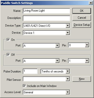 This window is where you enter information about
a paddle
switch. A paddle switch is a physical switch that actually is controlled
by two switches on an IO board, one to turn it on, and another to turn it
off. The IO board switches are momentarily turned on and off when to
change the state of the physical paddle switch.
This window is where you enter information about
a paddle
switch. A paddle switch is a physical switch that actually is controlled
by two switches on an IO board, one to turn it on, and another to turn it
off. The IO board switches are momentarily turned on and off when to
change the state of the physical paddle switch.
For the Name field, enter something that briefly and
uniquely describes the switch. Use the Description field if you
have any more information you want to put about the switch. These fields
will show up in the selection list and in the log file.
When you add a switch, you need to specify which type
interface device (Device Type) to use. Depending on what kind of
device you are using, there may also be more than one device for that type of
interface, so make sure you select the appropriate Device for the one you
want to use with this switch.
If On is checked, then you can enter the values
for the IO switch that turns the paddle switch on. If Off
is checked, then you can enter the values for the IO switch that turns the
paddle switch off. Usually you would wire it so the switch could be turned
both on and off, however if you only foresee the need to turn the switches off
automatically, and the switches will only be turned on manually, the off can be
omitted.
Then Port and Pin indicate the particular port and pin on
the IO board that are to be used for the switch. One pin will be used for
the On function and one will be used for the Off function. If the port is set to represent an entire byte rather than
individual pins, then the pin field will not be shown. The value for the
port will be between 0 and 255, where if each individual pin is used, the value
can only be 0 or 1.
Pulse Duration is the amount of time that an On or Off IO
switch will be turned on when changing the state of the paddle switch.
Generally, this value should be as small as possible while still functioning
reliably in order to preserve the life of your paddle switch.
The Pilot Sensor can be used if you have a sensor that
can detect if the device is on or off. This allows the status of the
switch to be updated even if it is manually switched.
If the Don't Show in Activity List check box is checked,
then when the switch is triggered, it won't show it in the log on the main
screen. This can be handy if it's a switch that is triggered frequently,
and you don't want it to clutter the log. By default, it will show up in
the log when it's triggered.
If the Include on Main Window is checked, then it will
appear on the "Switches" tab. The switches tab allows you to see
what switches have been triggered recently. It can also manually be
triggered from that window so you can simulate the switch being triggered.
By default, it will be shown in the switches tab on the main window.
The Access Level field indicates the access level a user
must have in order to control the switch. For instance, if the access
level is "General", and a user's item access level is
"Limited", they will not be able to trigger the switch from the
Switches tab on the main screen or from the network client, where if the user
has an item access level of "General" or Privileged", they will
be able to trigger it. If the access level is set to Privileged, then only
people with an item access level of "Privileged" will be able to
trigger the switch.
Home Domination Home
Page